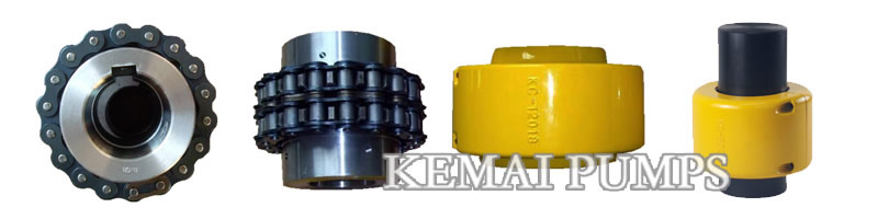
Chain coupling simple structure, convenient assembly, high torque and high efficiency. GL & KC series roller chain couplings not suitable high speed and vertical shaft link.
Chain coupling installation instructions
1:Chain couplings install flanges(sprockets) on shafts.If flanges are bushed type install per instructions packed with covers.
2:Align shafts.Some parallel and angular misalignment usually develops in usage because of shifting of the driving and driven units.Therefore,the shaft must be aligned as accurately as possible during installation to minimize wear.It will result in far longer service life with lower maintenance and operating cost.
3:Wrap chain around flanges and secure ends.Chain should move freely on flanges when coupling is properly aligned.
Chain Coupling Lubrication
1:Coupling without cover
Brush thoroughly at least once a week with a medium body machine or engine oil or with a good quality roller bearing grease of medium constancy.Particular attention to lubrication is required for coupling operating at high speeds.Re-lubricate frequently as required.
2:Coupling with cover.
- a:Work as good quality roller bearing grease of soft or medium consistency that minimun melting point of 260 degrees into the chain around its perimeter,being careful to coompletely lubricate the chain rollers and sprocket teeth.Do not use a cup or thick grease.
- b:Install roller chain coupling cover as per manufacturer’s insructions and fill with same grease.
3:Re-lubrication:Re-lubricate after initial 100 hours and once per year thereafter.
4:Check alignment and setscrews at the above same intervals.
GL Series roller chain coupling size and parameter:
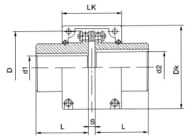
| Model | Nominal torsion Tn N·m | Speed [n] r/min | Shaft hole Diameter | Shaft hole length | Chain size | Chain pitch P | Number of teeth Z | D | S | Weight Kg | Rotate inertia kg·m2 | Limited compensation | ||||
| Y | J1 | Radial | Axial | Angle | ||||||||||||
| Without Cover | With Cover | d1,d2 | L、L1 | mm | mm | ° | ||||||||||
| GL1 | 40 | 1400 | 4500 | 16-20 | 42-52 | 38 | 0.6B | 9.525 | 14 | 51.06 | 4.9 | 0.4 | 0.00010 | 0.19 | 1.4 | 1° |
| GL2 | 63 | 1250 | 4500 | 19-24 | 42-52 | 38 | 0.6B | 9.525 | 16 | 57.08 | 4.9 | 0.7 | 0.00020 | 0.19 | 1.4 | 1° |
| GL3 | 100 | 1000 | 4000 | 20-25 | 52-62 | 38-44 | 0.8B | 12.70 | 14 | 68.88 | 6.7 | 1.1 | 0.00038 | 0.25 | 1.9 | 1° |
| GL4 | 160 | 1000 | 4000 | 24-32 | 52-82 | 44-60 | 0.8B | 12.70 | 16 | 76.91 | 6.7 | 1.8 | 0.00086 | 0.25 | 1.9 | 1° |
| GL5 | 250 | 800 | 3150 | 28-40 | 62-112 | 60-84 | 10A | 15.875 | 16 | 94.46 | 9.2 | 3.2 | 0.0025 | 2.3 | 2.3 | 1° |
| GL6 | 400 | 630 | 2500 | 32-50 | 82-112 | 60-84 | 10A | 15.875 | 20 | 116.57 | 9.2 | 5.0 | 0.0058 | 2.3 | 2.3 | 1° |
| GL7 | 630 | 630 | 2500 | 40-60 | 112-142 | 84-107 | 12A | 19.05 | 18 | 127.78 | 10.9 | 7.4 | 0.012 | 2.8 | 2.8 | 1° |
| GL8 | 1000 | 500 | 2240 | 45-70 | 112-142 | 84-107 | 16A | 25.40 | 16 | 154.33 | 14.3 | 11.1 | 0.025 | 3.8 | 3.8 | 1° |
| GL9 | 1600 | 400 | 2000 | 50-80 | 112-172 | 84-132 | 16A | 25.40 | 20 | 186.50 | 143. | 20.0 | 0.061 | 3.8 | 3.8 | 1° |
| GL10 | 2500 | 315 | 1600 | 60-90 | 142-172 | 107-132 | 20A | 31.75 | 18 | 213.02 | 17.8 | 26.1 | 0.079 | 0.63 | 4.7 | 1° |
| GL11 | 4000 | 250 | 1500 | 75-100 | 142-212 | 107-167 | 24A | 38.10 | 16 | 231.49 | 21.5 | 39.2 | 0.188 | 0.76 | 5.7 | 1° |
| GL12 | 6300 | 250 | 1250 | 85-120 | 172-212 | 132-167 | 28A | 44.45 | 16 | 270.08 | 24.9 | 59.4 | 0.380 | 0.88 | 6.6 | 1° |
| GL13 | 10000 | 200 | 1120 | 100-140 | 212-252 | 167-202 | 32A | 50.80 | 18 | 340.80 | 28.6 | 86.5 | 0.869 | 1.0 | 7.6 | 1° |
| GL14 | 16000 | 200 | 1000 | 120-160 | 212-302 | 167-242 | 32A | 50.80 | 22 | 405.22 | 28.6 | 150.8 | 2.06 | 1.0 | 7.6 | 1° |
| GL15 | 25000 | 200 | 900 | 140-190 | 252-352 | 202-282 | 40A | 63.50 | 20 | 466.25 | 35.6 | 234.4 | 4.37 | 1.27 | 9.5 | 1° |
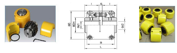
KC Series Chain Coupling size and data:
|
Coupling
Model |
Nominal torsion
N.m |
Max
Speed
r/min |
Shaft hole
d1 d2 |
Coupling Size/mm |
Weight
KG |
|||||||
|
D |
O |
DH |
L |
I |
S |
B |
Coupling |
Cover |
||||
|
KC 3812 |
99.9 |
6000 |
9-16 |
59 |
45 |
25 |
64.9 |
30 |
4.9 |
61 |
0.3 |
0.19 |
|
KC 4012 |
217 |
4800 |
11-22 |
75 |
61 |
35 |
79.4 |
36 |
7.4 |
75 |
0.8 |
0.33 |
|
KC 4014 |
295 |
4800 |
11-28 |
84 |
69 |
43 |
79.4 |
36 |
7.4 |
75 |
1.1 |
0.38 |
|
KC 4016 |
386 |
4800 |
16-32 |
92 |
77 |
50 |
87.4 |
40 |
7.4 |
75 |
1.6 |
0.41 |
|
KC 5014 |
562 |
3600 |
16-35 |
101 |
86 |
53 |
99.7 |
45 |
9.7 |
85 |
2.2 |
0.5 |
|
KC 5016 |
735 |
3600 |
18-40 |
111 |
96 |
60 |
99.7 |
45 |
9.7 |
85 |
2.8 |
0.58 |
|
KC 5018 |
931 |
3000 |
18-45 |
122 |
107 |
70 |
99.7 |
45 |
9.7 |
85 |
3.6 |
0.66 |
|
KC 6018 |
1750 |
2500 |
22-56 |
142 |
128 |
85 |
123.5 |
56 |
11.5 |
106 |
6.5 |
0.96 |
|
KC 6022 |
2370 |
2500 |
28-71 |
167 |
152 |
110 |
123.5 |
56 |
11.5 |
106 |
10.3 |
1.3 |
|
KC 8018 |
3880 |
2000 |
32-80 |
186 |
170 |
115 |
141.2 |
63 |
15.2 |
130 |
13.8 |
2.0 |
|
KC 8022 |
5580 |
2000 |
40-100 |
220 |
203 |
140 |
157.2 |
71 |
15.2 |
130 |
21.7 |
2.5 |
|
KC 10020 |
8780 |
1800 |
45-110 |
250 |
233 |
160 |
178.8 |
80 |
18.8 |
148 |
32.6 |
3.7 |
|
KC 12018 |
13200 |
1500 |
50-125 |
307 |
256 |
170 |
202.7 |
90 |
22.7 |
181 |
43.9 |
3.3 |
|
KC 12022 |
17100 |
1200 |
56-140 |
357 |
304 |
210 |
222.7 |
100 |
22.7 |
181 |
69 |
3.9 |
|
KC 16018 |
28600 |
1000 |
63-160 |
406 |
341 |
224 |
254.1 |
112 |
30.1 |
250 |
96.3 |
14.7 |
|
KC 16022 |
41700 |
1000 |
80-200 |
472 |
405 |
280 |
310.1 |
140 |
30.1 |
250 |
166.8 |
17.2 |